| |
|
|


|
|
Selecting and Using RS-232, RS-422, and RS-485 Serial Data Standards
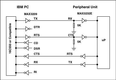
"The great thing about standards is there are so many to choose from." This statement was made at a recent conference on fiber optics, and it holds true for electrical-interface standards as well. Serial-data standards tend to evolve separately, within particular industries, thus we have more standards than we should. Perhaps the most successful serial-data standard for PC and telecom applications is the RS-232. Similarly, the RS-485 and RS-422 are among the most successful standards for industrial applications. These standards are not directly compatible, however for purposes of control and instrumentation it is often necessary to communicate between them. This article offers insight into the different standards (electrical physical-layer specifications), how to convert from one standard to another standard, and how to combine different standards within the same application. The RS-232 link was initially intended to support modem and printer applications on IBM PCs, however it now enables a variety of peripherals to communicate with PCs. The RS-232 standard was defined as a single-ended standard for increasing serial-communication distances at low baud rates (< 20kbps). Over the years the standard has changed as necessary to accommodate faster drivers like the MAX3225E, which offers 1Mbps data-rate capability. For RS-232 compliance, a transceiver such as the MAX3225E must meet the electrical specifications listed in Table 1. A typical connection (Figure 1) shows the use of hardware handshaking to control the flow of data.
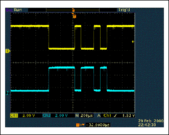
A typical RS-232 signal (Figure 2, CH1) swings positive and negative;
note the relative location of the 0V trace markers on the left axis.
Although the RS-232 data is inverted, an overall translation from TTL/CMOS
to RS-232 and back to TTL/CMOS restores the data's original polarity.
Typical RS-232 transmissions seldomly exceed 100 feet for two reasons: The
difference between transmitted levels (±5V) and receive levels (±3V)
allows for only 2V of common-mode rejection, and the distributed
capacitance of a longer cable can degrade slew rates by exceeding the
maximum specified load (2500pF). Since the RS-232 was designed as a
point-to-point rather than multi-drop interface, its drivers are specified
for single loads from 3k
Daisy-Chain Devices To eliminate the problems associated Daisy-Chain networks Maxim
developed the MAX3322E/MAX3323E, which are specifically designed to be
configured in multi-drop applications. These unique devices employ a
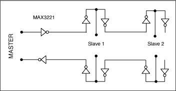
logically switched input resistance of 5k Another solution would be to convert the RS-232 RX and TX signals to an RS-422 signal (see Table 2). RS-422 is a differential standard that allows transmission over much greater distances. The higher input resistance of RS-422 inputs, combined with their higher drive capability, allows a connection of up to 10 nodes (Figure 4). Another advantage of RS-422 is the separate transmit and receive paths, for which no direction control is needed. Any necessary handshaking between devices can be performed with either software (XON/OFF handshaking) or hardware (a separate set of twisted pairs). The MAX3162 provides an economical way to translate between RS-232 and RS-422 signals. For more detail, refer to the section titled "RS-232/RS-485 Protocol Translators".
RS-422 and RS-485 transceivers are often confused with each other; one
is assumed to be a full-duplex version of the other. However the
electrical differences in their common-mode ranges and receiver-input
resistances suit these standards for different applications. Since the
RS-485 meets all of the RS-422 specifications (Table 3), RS-485 drivers
can be used in RS-422 applications. The opposite, however, is not true.
The common-mode output range for RS-485 drivers is -7V to +12V, where as
the common-mode range for RS-422 drivers is only ±3V. The minimum
receiver-input resistance is 4k Table 1. RS-232 Summary of Major Electrical Specifications
Table 2. RS-422 Summary of Key Specifications
Table 3. RS-485 Summary of Key Specifications
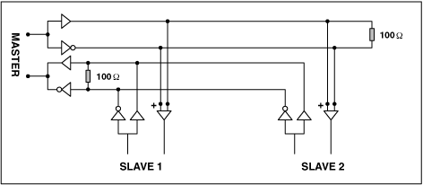
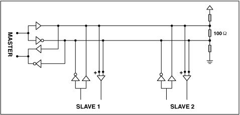
To reduce wiring expense and achieve longer line lengths, RS-485 transceivers have become a popular standard for use in point-of-sale, industrial, and telecom applications. Its wider common-mode range also enables longer line lengths and a higher input resistance per node, allowing more nodes to be connected to the bus (Figure 5).
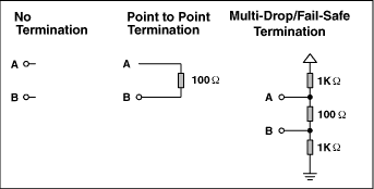
Differential RS-485 transmissions (Figure 6) produce opposing currents and magnetic fields along each segment (wire) of a twisted-pair cable; thus minimizing the emitted electromagnetic interference (EMI) via cross-canceling of the opposing fields around each wire. For transmissions through a long cable or at high data rates, the cable appears as a transmission line and should be terminated with the cable's characteristic impedance. This aspect of the RS-485 connection causes confusion. Does the line need to be terminated, and if so how should it be terminated? If the designer is not the end user, should these questions be left for the installer to figure out? For most RS-485 transceivers, the data sheet indicates a simple choice between no termination, and a simple point-to-point termination when the cable acts as a transmission line (Figure 7). A termination resistor across the A-B terminals is harmless. By default, the transmission line should be terminated at the last transceiver on the line (bus).
Fail-Safe Unfortunately, different runs of chips can produce different output signals on RO for a 0V differential input. The prototype can work perfectly, however certain nodes will fail in a later production run. To solve this problem, bias the bus as shown in Figure 7 (Multi-Drop/Fail-Safe Termination). Biasing the bus ensures that the receiver output remains "1" when the bus is tri-stated. Or, you can use "True Fail-Safe" receivers like those of the MAX3080 (5V) and MAX3070 (3V) families. These devices ensure an RO output of "1" in response to a 0V differential input by changing the receiver's threshold to -50mV. RS-232/RS-485
Protocol Translators
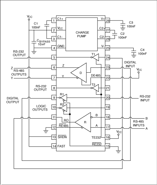
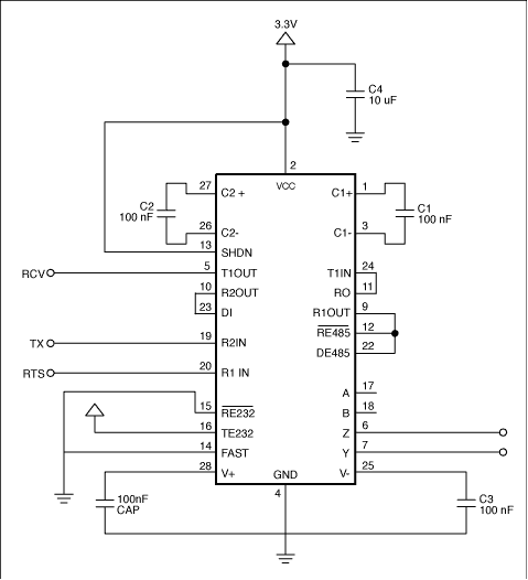
Figure 9 shows the MAX3162 configured as an RS-232/RS-485 multi-point protocol translator. The direction of translation is controlled through the RTS signal R1IN. The single-ended RS-232 receiver input signal is translated to a differential RS-485 transmitter output. Similarly, a differential RS-485 receiver input signal is translated to a single-ended RS-232 transmitter output. RS-232 data received on R2IN is transmitted as an RS-485 signal on Z and Y. RS-485 signals received on A and B are transmitted as an RS-232 signal on T1OUT. The RTS line offers a common means for controlling bus direction in circuits that convert from RS-232 to RS-485. This line on the RS-232 port controls whether the RS-485 transceiver acts as a transmitter or a receiver (Figure 9). Note that the system cannot be sure that a byte of data in the UART's transmit buffer has been transmitted unless the system monitors the RS-485 driver input (DI). That is, the system must either allow for a fixed time delay or actively monitor the DI input before using the DE input to change the bus direction. Other direction-control techniques include using a microcontroller and
driving the DE input with data while pulling the A-B lines apart
(connecting a pull-up resistor from A to 5V and connecting a pull-down
resistor from B to ground). The value of these resistors varies with cable
capacitance, but is typically 1k
Port-Powered Devices Hot-Swap References
| |||||||||||||||||||||||||||||||||||||||||||||||||||||||||||||||||||||||||||||||||||||||||||||||||||||||||||||||||||||||||||||||||||||||||||||||||||||||||||||||||||||||||||||||||||||||||||
|
 to 7k
to 7k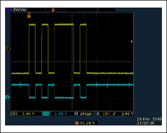
 LINK TO US